| 1. Introduction: |
| Although a long time has elapsed since the introduction of the Merlin XX engine into the Hurricane, and although several reports have already been issued on the results of tests made of Hurricane II’s, this report deals with the results of tests made on the aeroplane as a type and is designed to be used as a basis for comparative results either already obtained or to be obtained in the future.
2. Condition of aeroplane relative to tests: The aeroplane appears as a Mark IIA, B, or C. The Mark IIA is further sub-divided into Series 1 and 2 according to whether the longerons are unstrengthened or strengthened. The suffix A denotes the installation of 8 - .303 guns in the wings, the B denotes 12 - .303 inch guns in the wings and C denotes 4-20 mm guns in the wings. From the above it will be seen that one of the aeroplanes tested had 12 - .303 inch guns installed and the other 8 - .303 inch guns. Throughout the tests the gun ports were sealed. One of the aeroplanes Z.3564, was first used for tests of under-wing fuel tanks, but for the tests detailed in this report the under-wing tanks were removed and the aeroplane made standard. All performance measurements were made on Z.3564 but this aeroplane was taken away for special tests at the firm and handling trials were completed on Z.2346. Other conditions applicable to both aircraft were as follows: no snowguard was fitted, a rear-view mirror was mounted on top of the pilot’s hood outside, and triple-ejector exhausts were fitted (without fishtails). 3. Loading of aircraft: Throughout the trials the aircraft were loaded as follows: |
| Aeroplane | Loading | Weight (lb) | C.G. (inches aft of datum) |
| Z.3564 | Extended aft limit | 7397 | 59.6 |
| Z.2346 | Forward limit | 6558 | 56.3 |
| The typical service load produces the aft limit so the 1% A.M.C. extension was added to the C.G. position of Z.3564 in order to save re-loading the aeroplane later for handling tests. The extension was arrived at by the addition of 64 lb. of ballast.
4. Results of tests: |
| AEROPLANE | Hurricane IIb | No. Z.3564. |
| SPEC. No. | ||
| CONTRACT. | ||
| CONTRACTOR. | Hawker Aircraft Co. |
| TYPE | Single-engine monoplane | DUTY | Fighter. |
| ENGINES. | Merlin XX. | Normal B.H.P | 1255 at Rated Altitude 10,000 ft. |
| " " | 1190 at Rated Altitude 18,500 ft. | ||
| At 2,850 R.P.M. and +9 lb. boost | |||
| " 2,850 R.P.M. and +9 lb. boost | |||
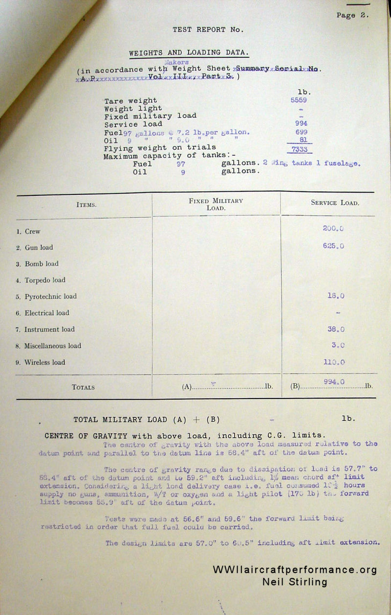
| lb. | |
| Tare weight | 5559 |
| Weight light | |
| Fixed military load | |
| Service Load (including 64 lb. ballast) | 1058 |
| Fuel 97 gallons* | 699 |
| Oil 9 | 81 |
| Flying weight on trials. | 7397 |
| At Full Throttle | |||||||||||||||||||||||||||||||
| Height Feet | Speed M.P.H | Time to Climb Mins | Rate of Climb ft/min | ||||||||||||||||||||||||||||
| S.L | 0 |
| 2,000 | | 0.7 | 2710
| 5,000 | | 1.8 | 2710
| 10,000 | 294 | 3.7 | 2510
| 15,000 | 303 | 5.9 | 2150
| 20,000 | 326 | 8.5 | 1740
| 25,000 | 330 | 8.8 | 1690
| 30,000 | 309.5 | 17.0 | 720
| | |
| Service ceiling 35,900 ft. | Landing speed M.P.H |
| Take off run Time. secs | Distance from rest to clear ft. screen yds. |
| Stalling speed M.P.H | Gliding in A.S.I. M.P.H. |
| Best landing A.S.I. M.P.H | Distance to rest (with brakes) After clearing 50 ft. screen . |
| Landing and take off tests corrected to | |
| AIRCRAFT | Hurricane II. Z.3554. |
| ENGINE | Merlin XX. No. 26687/188972. |
| Position | Centre. | ||
| Variable Pitch Airscrew. | Rotol C.S. | ||
| Type. | R.S.5/3. | ||
| Serial No. | 18436 | ||
| Diameter. | 11' 3" | ||
| No. of Blades | 3 | ||
| Direction of rotation. | R.H. | ||
| Serial Nos.- Hub. | 18436 | ||
| " " " Blade No.1 | JP 10461 | ||
| " " " " No.2 | JP 10190 | ||
| " " " " No.3 | JP 10460 | ||
| Basic pitch setting. | Not stated. | ||
| Pitch range. | 35° | ||
| High pitch setting. (Measured) | 65° - 7' | ||
| Low pitch setting. | 30° - 7' |
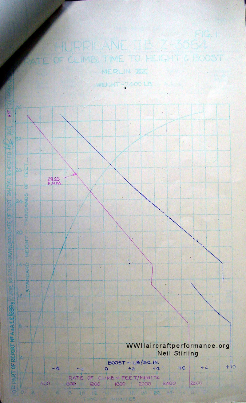
| Height in Standard Atmosphere Feet | Time From Start Min. | Rate of Climb Ft./Min. | True Air Speed M.P.H. | A.S.I. M.P.H. | Compressibility & Position Error Correction Comp. | P.E.C. | R.P.M. | Boost lb./sq. in. | Radiator Blower | |
| Sea Level | 0 | Controlling at 2850 R.P.M. | M | ||||||
| 1,000 | 0.4 | 2710 | 145.5 | 142 | 0 | +1.4 | +9.8 | ||
| 2,000 | 0.7 | 2710 | 147.5 | 142 | 0 | +1.4 | +9.8 | ||
| 3,000 | 1.1 | 2710 | 150 | 142 | -0.1 | +1.4 | +9.8 | ||
| 5,000 | 1.8 | 2710 | 154.5 | 142 | -0.1 | +1.4 | +9.8 | ||
| 6,500 | 2.4 | 2710 | 156 | 142 | -0.2 | +1.4 | +9.8 | ||
| 10,000 | 3.7 | 2510 | 166.5 | 142 | -0.3 | +1.4 | +8.7 | ||
| 13,000 | 5.0 | 2610 | 174.5 | 142 | -0.4 | +1.4 | +7.0 | ||
| 15,000 | 5.9 | 2150 | 180 | 142 | -0.5 | +1.4 | +9.4 | S | |
| 16,500 | 6.6 | 2150 | 184.5 | 142 | -0.5 | +1.4 | +8.8 | ||
| 18,000 | 7.4 | 1940 | 186.5 | 140 | -0.6 | +1.5 | +7.8 | ||
| 20,000 | 8.5 | 1740 | 190.5 | 138 | -0.7 | +1.6 | +6.3 | ||
| 23,000 | 10.3 | 1440 | 186.5 | 135 | -0.7 | +1.9 | +4.2 | ||
| 26,000 | 12.7 | 1130 | 202.5 | 132 | -0.9 | +2.1 | +2.0 | ||
| 28,000 | 14.6 | 920 | 207 | 130 | -1.0 | +2.3 | +0.8 | ||
| 30,000 | 17.0 | 720 | 212 | 128 | -1.1 | +2.5 | -0.5 | ||
| 32,000 | 20.4 | 510 | 216.5 | 126 | -1.1 | +2.6 | -1.7 | ||
| 34,000 | 25.6 | 300 | 215 | 120 | -1.1 | +3.2 | -2.8 | ||
| 35,000 | 29.8 | 200 | 205.5 | 111 | -0.9 | +4.1 | -3.3 | ||
| * 8,300 | 3.0 | 2710 | 162.5 | 142 | -0.2 | +1.4 | +9.8 | M | |
| ** 15,700 | 6.2 | 2160 | 182 | 142 | -0.5 | +1.4 | +9.4 | S | |
| Estimated absolute ceiling 38,800' | Greatest height reached. 35,900 ft |
| R.P.M. stationary on ground. | Boost pressure lb./sq.in. |
| * Full throttle height. *8,300 ft. in 'M' blower. **15,700 ft. in 'S' blower. | |
| ** Service ceiling. 35,900' (Estimated) | |
| Note1:- For position error correction curve and position of pressure head see Fig. 13 in 15th Part of Report A.& A.E.E./689. | |
| Height in Standard Atmosphere Feet | True Air Speed M.P.H. | A.S.I. M.P.H. | Compressibility and Position Error Correction P.E.C. | Comp. | R.P.M. | Boost lb./sq. in. | Blower gear. | |
| Sea Level | 3000 | ||||||
| 1,000 | |||||||
| 2,000 | |||||||
| 3,000 | |||||||
| 5,000 | |||||||
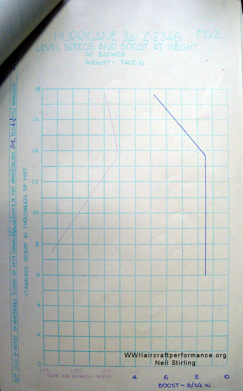
| 8,000 | 288 | 261.5 | -5 | -1.3 | +9 | M | |
| 10,000 | 294 | 259 | -4.9 | -1.6 | +9 | ||
| 13,000 | 305 | 256.5 | -4.8 | -2.1 | +9 | ||
| 15,000 | 303 | 247 | -4.5 | -2.3 | +7.4 | ||
| 16,500 | 301.5 | 240 | -4.2 | -2.4 | +6.0 | ||
| 18,000 | 316.5 | 247 | -4.7 | -3.2 | +8.8 | S | |
| 20,000 | 326 | 246 | -4.5 | -3.5 | +8.8 | ||
| 23,000 | 329 | 235.5 | -4 | -3.7 | +7 | ||
| 26,000 | 324 | 220.5 | -3.4 | -3.8 | +4.7 | ||
| 28,000 | 318 | 208 | -2.8 | -3.7 | +3.1 | ||
| 30,000 | 309.5 | 194.5 | -2 | -3.5 | +1.6 | ||
| * 20,800 | 330 | 246 | -4.5 | -3.6 | +8.8 | ||
| Landing and take off tests corrected to zero wind and standard atmosphere. | |
| Take off run (a) 280 (b) 235 yds with (a) 5° (b) 35° Flap | Time - secs. |
| Distance from rest to clear 50 | foot screen (a) 420 yds. |
| Gliding in A.S.I. M.P.H. | Stalling speed (b) 440 M.P.H./Kts. |
| Best landing A.S.I. M.P.H. | |
| Distance to rest (with brakes) after passing over 50 ft. screen yds. | |
| Landing run with brakes yds. | Landing run without brakes yds |
| Under conditions of test. that is, Wind 9.0 m.p.h. pressure 29.99 "Hg. Ground temperature 17°C. | |
| Take off run. (a) 210, (b) 195 yds | |
| Distance from rest to clear 50 ft. screen = (a) 400, (b) 375 yds. | |
| * Full Throttle Height | |
| Note 1:- For position error correction curve and position of pressure head see Hurricane II curve Fig.13 in 15th Part of Report AAEE/689. | |
| WEIGHT AND LOADING DATA | |
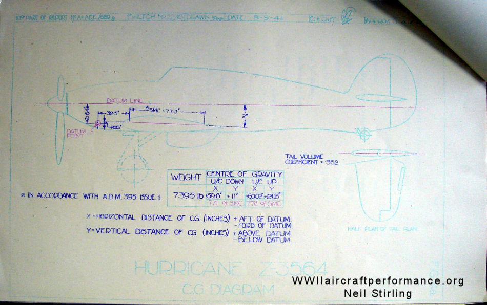
| CG DIAGRAM | |
| RATE OF CLIMB & TIME TO HEIGHT | |
| LEVEL SPEEDS & BOOST AT HEIGHTS | |