FLIGHT TEST DIVISION
MEMORANDUM REPORT NO. TSFTE-2029
14 October 1946

FLIGHT TEST OF THE P-51H AIRPLANE, AAF NO. 44-64182

I         Introduction

          A.     Flight tests have been conducted at Wright Field on the P-51H airplane No. 44-64182, at the request of the Production Section, Procurement Division. The tests were flown by Captain John W. McGuyrt, Fighter Operations Section, Flight Test Division, for a total of approximately 48 hours. AN-F-33 fuel was used throughout the tests, making it possible to obtain up to 90 inches of mercury manifold pressure with water injection.

          B.     The original intent of the request was for complete performance data, but due to a series of interruptions the airplane did not arrive at Wright Field until the later part of December 1945. During this delay the contractor obtained performance and range data on a similar P-51H airplane and sent the information to Chief, Technical Data Laboratory, Engineering Division for preparing the figures presented (in black) in the performance tables in the T. O. for this airplane. For this reason the scope of the tests was limited primarily to obtaining data for checking the contractor’s figures.

II       Conclusions

          A.     Control and handling characteristics of the P-51H are good under the conditions tested with the exception of a slight tendency to hunt directionally at indicated speeds above 400 mph. The elevator tab is inadequate for level flight trim when flying at 3000 rpm and 90” manifold pressure.

          B.     The performance results in this report are satisfactory for use in checking the figures presented in the Technical Order.

III      Recommendations

          It is recommended that:

          A.     Additional nose down elevator trim be provided.

IV      Condition of the Aircraft Relative to Tests

          A.     The P-51H differs from earlier models in that the fuselage lines are somewhat cleaner, the wing has been redesigned for lower drag, the empennage section has also been redesigned and the airplane is equipped with four bladed Aero Products propeller

          B.     All tests at the fighter configuration (bomb and rocket racks only) were flown at a take-off weight of 9544 lbs. and approximately 25.4% M.A.C., wheels up, and 25.9% M.A.C., wheels down. This included ballast for 1820 rounds of 50 caliber ammunition, six 50 caliber guns, and a full supply of fuel, oil, and water.

          C.     Items were added to the airplane at the gross weight to obtain the following configurations and corresponding take-off weights. One additional flight was made for each condition to measure the drag of the external equipment.


Flight No.ConfigurationTake-off
Gr. Wt. Lbs.

16Two 1000 Lb. Bombs11,545
17Six 5" HVAR Rockets and Two 500 Lb. Bombs11,345
18Ten 5" HVAR Rockets10,880
19Six 5" HVAR Rockets and Two 110 Gal. Tanks11,860
20Two 500 Lb. Bombs10,525
21Two 110 Gal. Tanks.11,040

 
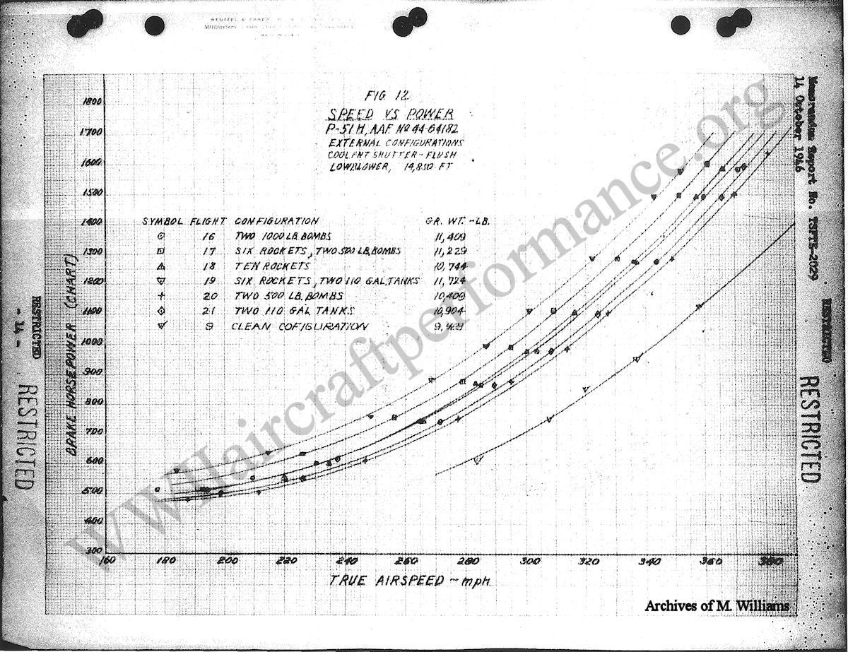
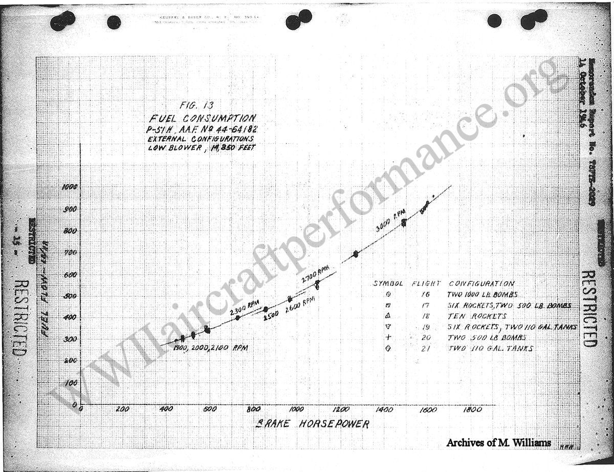
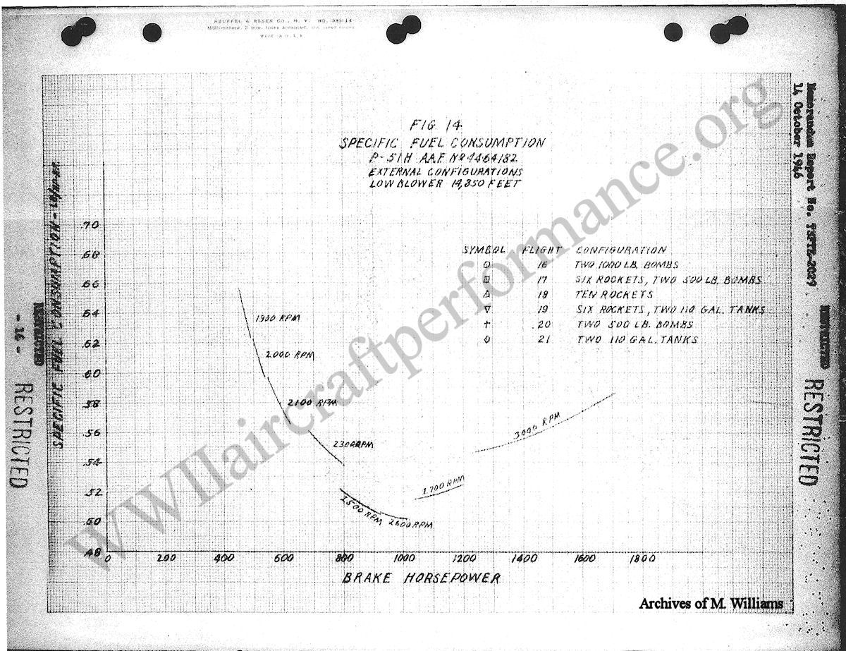
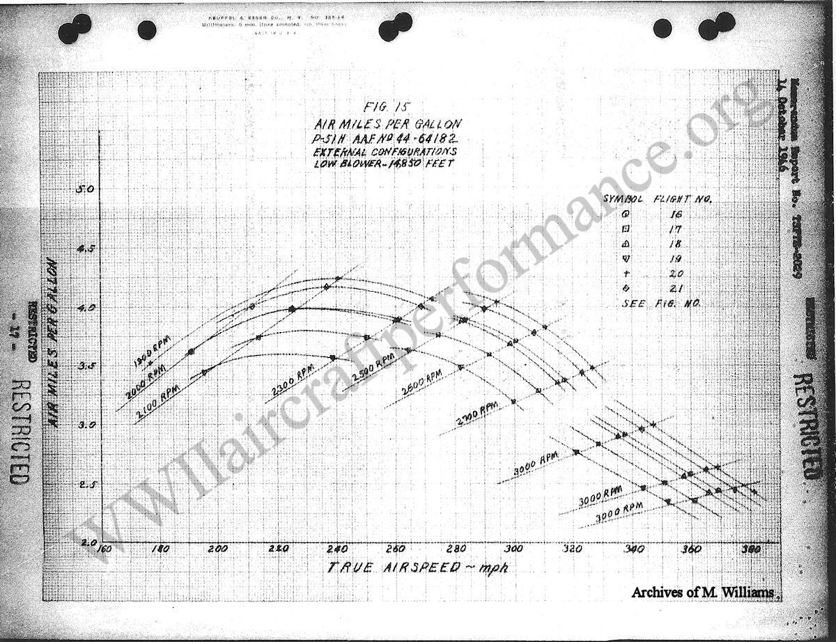
                   For flight 18 (10 rockets) it was necessary to replace each bomb rack with two rocket racks. For flights 19 and 21, the tanks were loaded with 79 gallons of water, each, to simulate the weight of fuel.

          D.     The airplane was equipped with a Packard built Rolls Royce model V-17650-9 engine, equipped with water injection for use at war emergency powers exceeding 67" Hg. manifold pressure, a Bendix Stromberg PD-18C-3A carburetor, and a 11' – 1" diameter four-bladed Aero Products propeller H-20-162-29M5, design No. 86892.

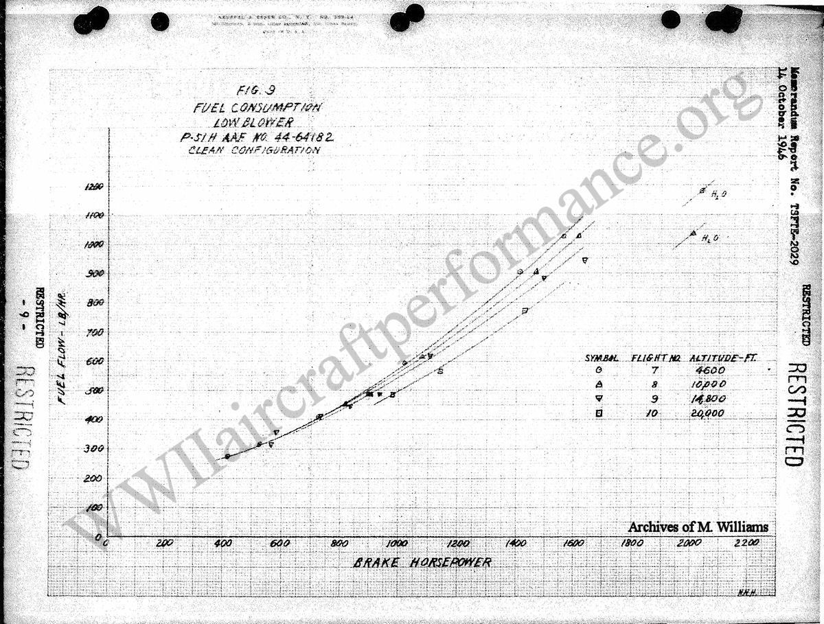
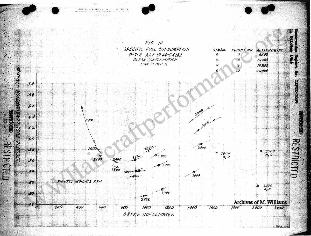
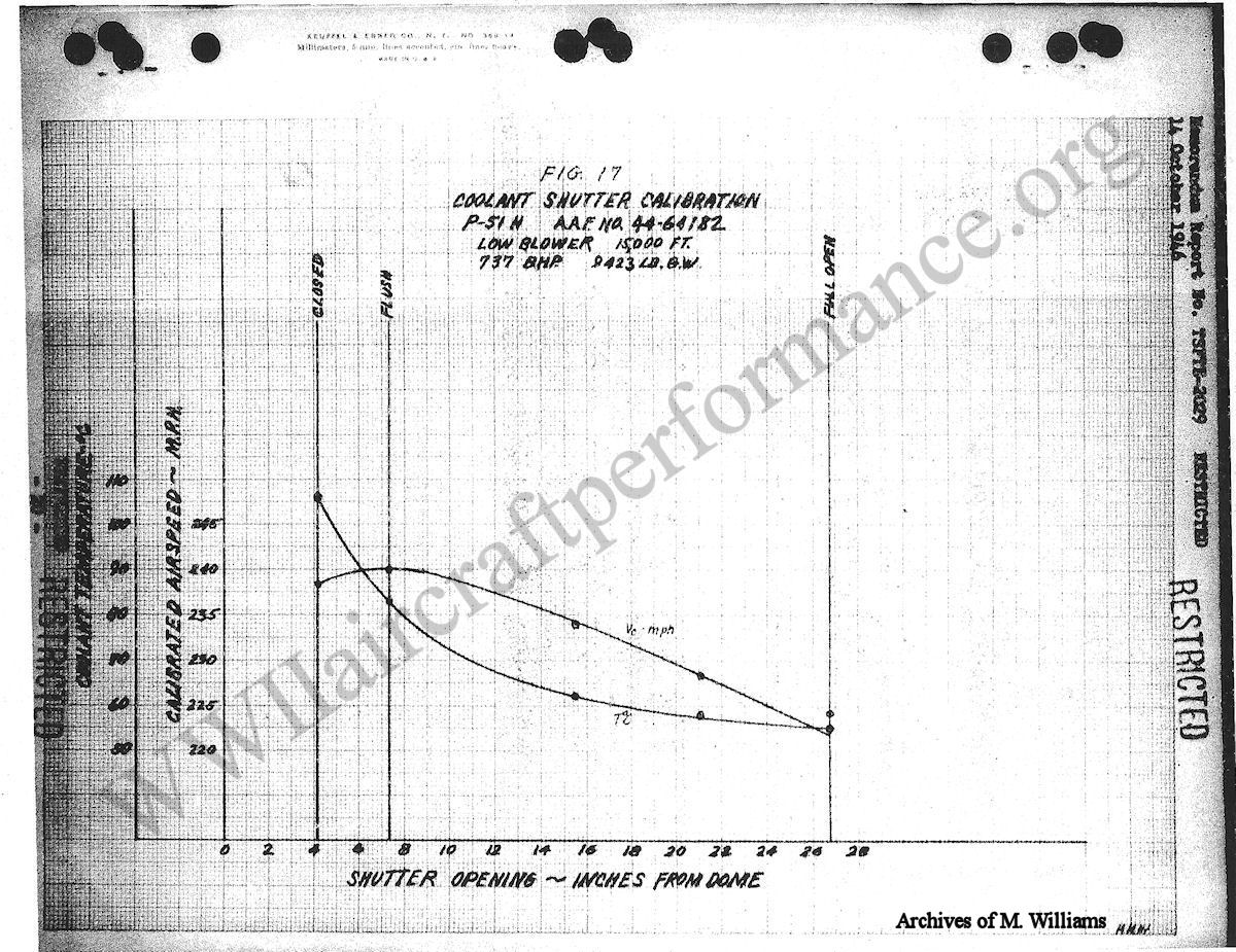
          E.     All flights were made with wheels up, flaps neutral, canopy closed, mixture "run", and manual boost control. The airplane has a normal unpainted finish. All level flight power calibrations were run with the coolant shutter in the flush position. Climbs were run with the coolant shutter in automatic. All horsepower figures are based on power curves Nos. 2493 and 2494 dated 2 November 1945, furnished by the Power Plant Laboratory.

V        Flight Characteristics

          A.     Taxiing and Ground Handling

                   The airplane has good ground handling characteristics. The tail wheel is steerable 6° either side of center, and is held securely in the steerable position when the control stick is in neutral or aft of neutral. When the control stick is held in the forward position, the tail wheel is full swiveling and brakes must be used for control and slow speeds. Forward visibility is not improved materially in this model when in the 3 point attitude, making "S" turns necessary for forward vision. Ground handling can be easily accomplished in cross-winds.

          B.     Take-off and Climb

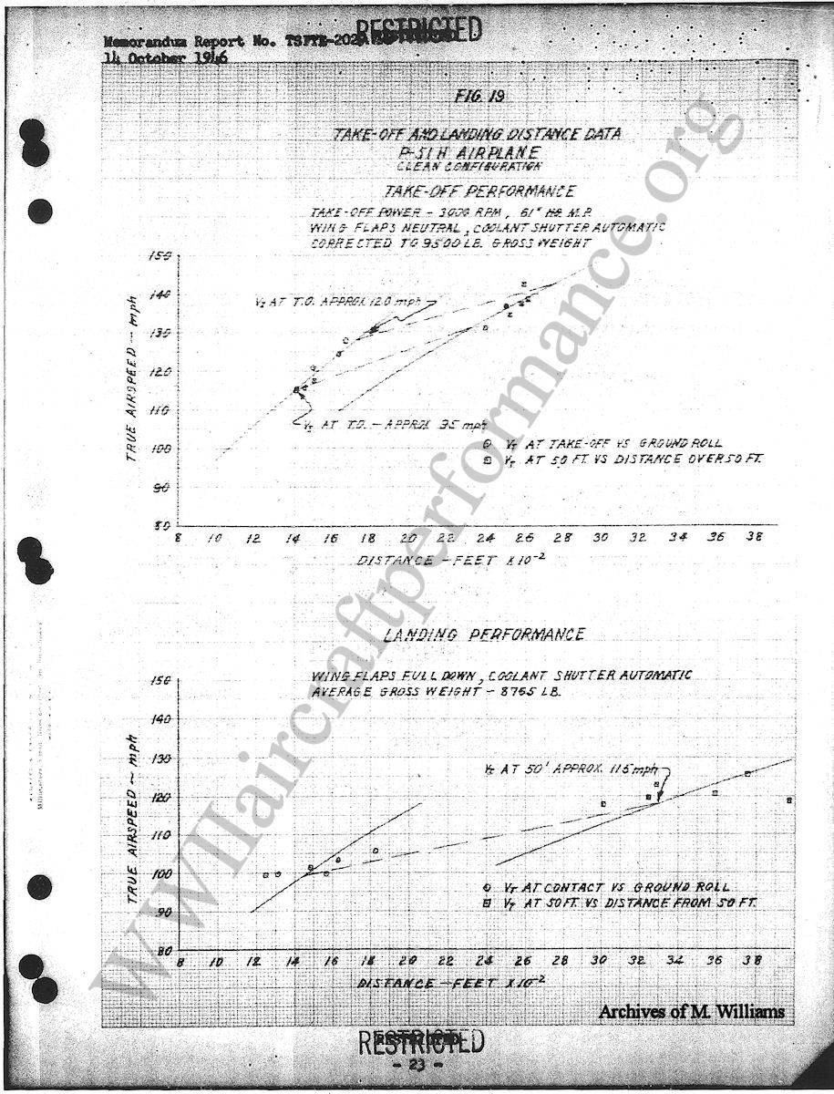
                   Take-off characteristics are normal. The take-off power setting is 3000 rpm and 61" Hg. For short field operation and best obstacle clearance, 15 to 20 degrees of flaps should be used, rudder trim should be set 7° right, elevator 1° nose heavy, and the Aileron tab in the neutral position. The slowest take-off speed attempted was approximately 103 mph, indicated.

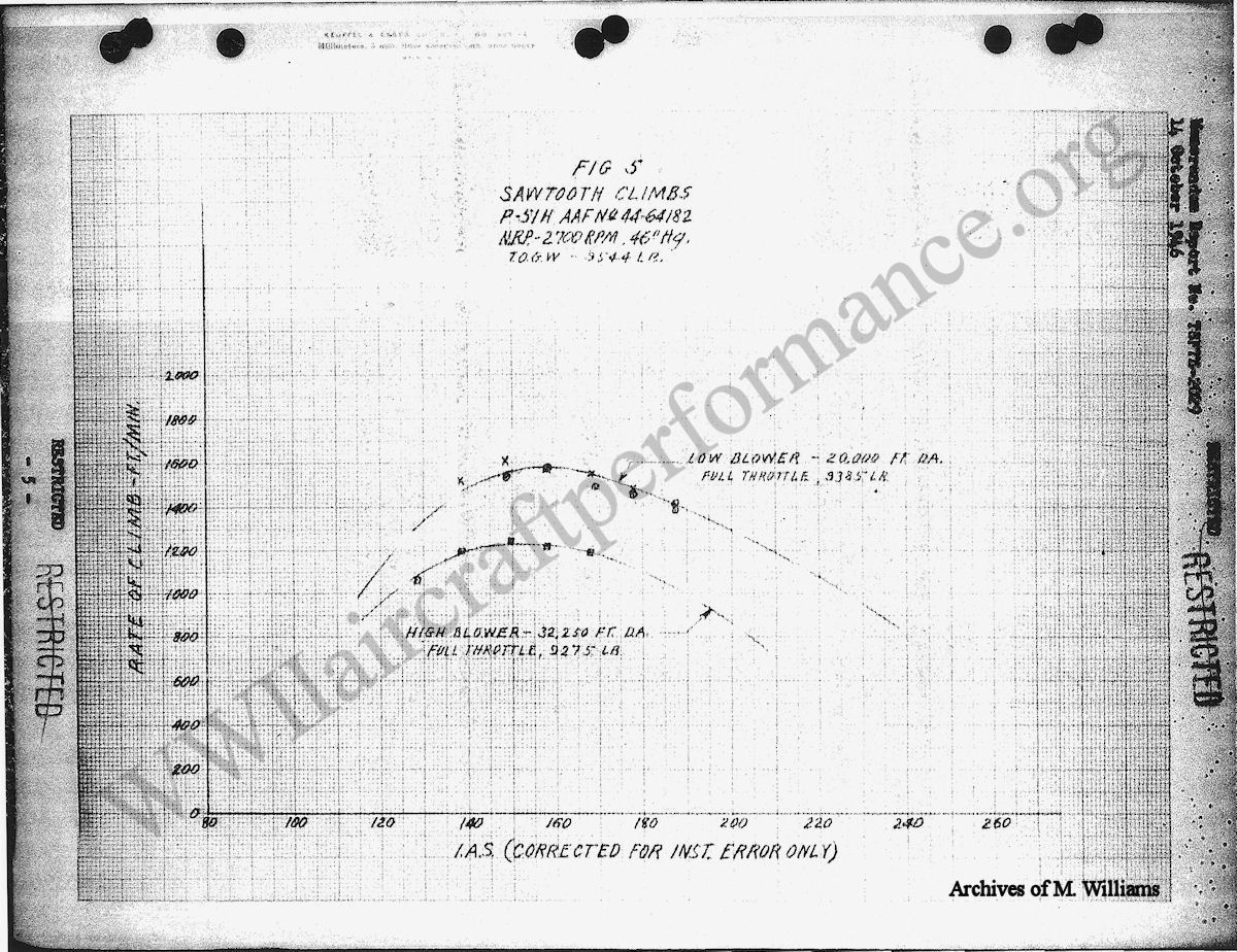
                   Sawtooth climbs indicated the best climb speed to be approximately 162 mph IAS for low blower and 154 mph IAS for high blower.

          C.     Stability.

                   No extensive stability investigation was made. Aside from a slight tendency to "hunt" directionally above 400 mph IAS, the characteristics were good and no deviation from previously reported characteristics was noted.

          D.     Trim and Balance.

                   Trim tabs are located on all control surfaces. Any varaiation in airspeed and power or external configuration which require a change in trim in the normal operating range may be easily corrected. However, at the high manifold pressures approaching 90" Hg. where water injection is necessary, the elevator trim is inadequate and it is necessary to exert excessive forward pressure on the control stick to maintain level flight.

          E.     Controllability.

                   The airplane has good control characteristics throughout the speed range except for the insufficient nose down trim mentioned in the preceding paragraph.

          F.     Maneuverability.

                   The airplane is very maneuverable within the range of speed tested. The radius of turn is comparatively small and the rate of roll is high. No buffeting is encountered in tight turns until the stalling speed is approached.

          G.     Stalling Characteristics.

                   Stalling characteristics were good in all configurations. The stalls were not violent, the approach was easily controlled and recovery was easily accomplished in all cases. The airplane enters the stall gradually, giving the pilot a sensation of mushing instead of complete stall.

          H.     Spinning Characteristics.

                   Not investigated.

          I.      Diving Characteristics.

                   Not investigated. See Memorandum Report No. TSCEP5E-1898.

          J.      High Altitude Trials.

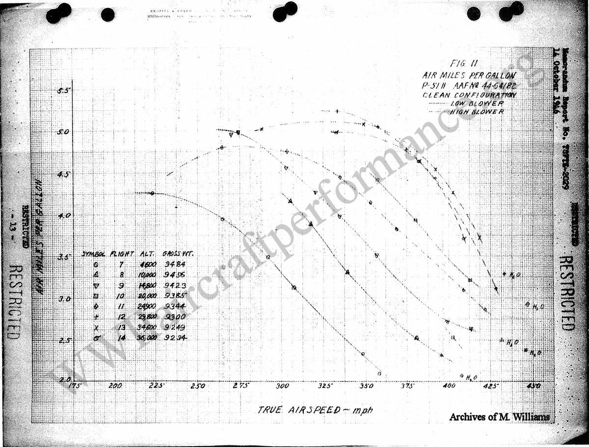
                   Under test conditions, the pilot determined 36,000 ft. to be the maximum practical condition for cruising. At this altitude three satisfactory level flight points using 3000, 2700 and 2500 rpm were obtained. Above 36,000 ft. the maximum level flight indicated airspeed at normal rated rpm begins decreasing rapidly with altitude.

                   No serious difficulty with freezing of trim tabs or other low temperature conditions were encountered.

          K.     Approach and Landing.

                   The approach is normal, the landing flaps operate quickly and there is very little tendency to float. Visibility is good with the gear down and is increased slightly when the flaps are lowered. Normal landing speed is approximately 102 mph IAS, normal speed for the glide is between 120 and 125 mph. The P-51H is easily controlled on the landing roll with the steerable tail wheel or brakes and has no ground looping tendencies. Final trim tab settings (power off) and landing is 2° right rudder and 9° nose up elevator.

          L.     Noise and Vibration.

                   Noise level is normal and not objectionable except when using over 74" Hg., MP. Most of the noise is caused by the short exhaust stacks just forward of the pilot. Vibration is slight above 420 IAS, below that it is negligible. There is little buffeting of the controls except with gear and flaps down. Vibration increases below 2000 rpm.

          M.     Pilot’s Report on Vision and Cockpit Layout.

                   The visibility in taking, take-off and climb is normal for single engine aircraft. In the air, in level flight, visibility for combat and cross country is good. The visibility on approach for landing is satisfactory. There are no distortions in the side windshield, canopy, or bullet proof glass. The P-51H is equipped with the standard AAF bucket type seat. Shoulder and elbow room is sufficient. Rudder pedals are in a comfortable position, however, the control stick is mounted slightly forward of the desired position.

VI      Performance Data

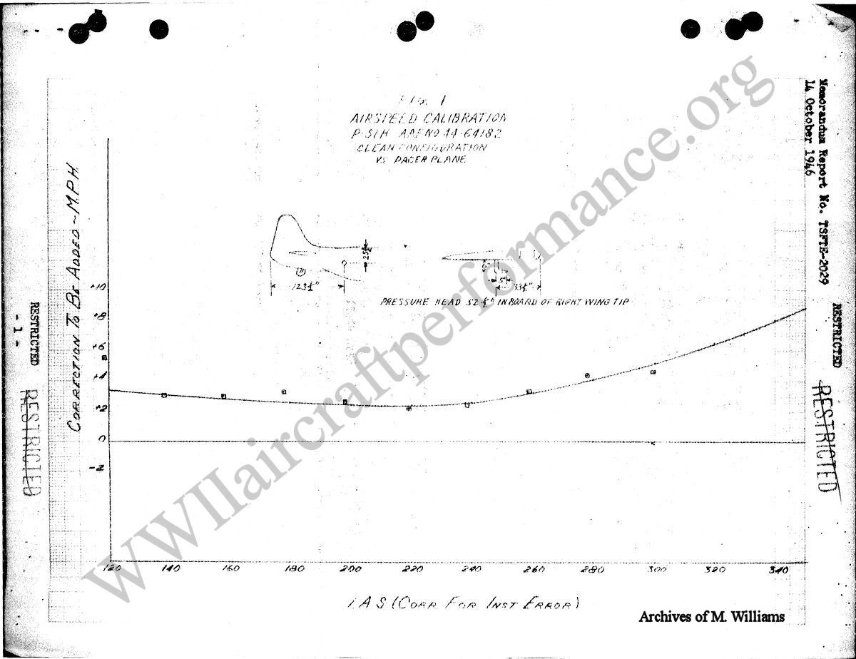
          A.     Airspeed Indicator Calibration.

                   The airspeed position correction was obtained by flying with the P-51D, AAF No. 44-74570 pacer airplane. The results of the calibration and the location of the impact and static pickups may be found by referring to Figure 1, Appendix I. All indicated airspeeds quoted in this report are corrected for instrument error only.

          B.     Altimeter Correction.

                   The altimeter calibration was calculated for the position error of the airspeed pickup and is presented in Figure 4, Appendix I.

          C.     Critical Altitude.

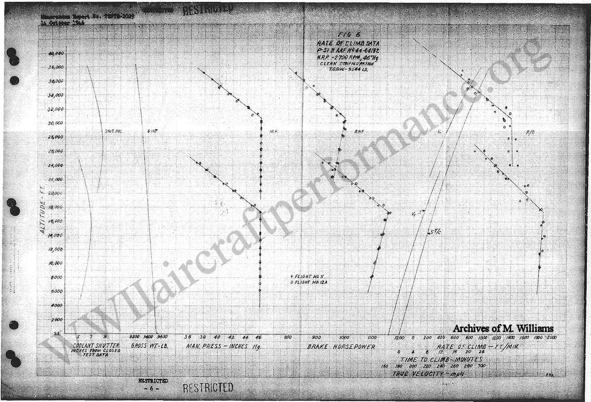
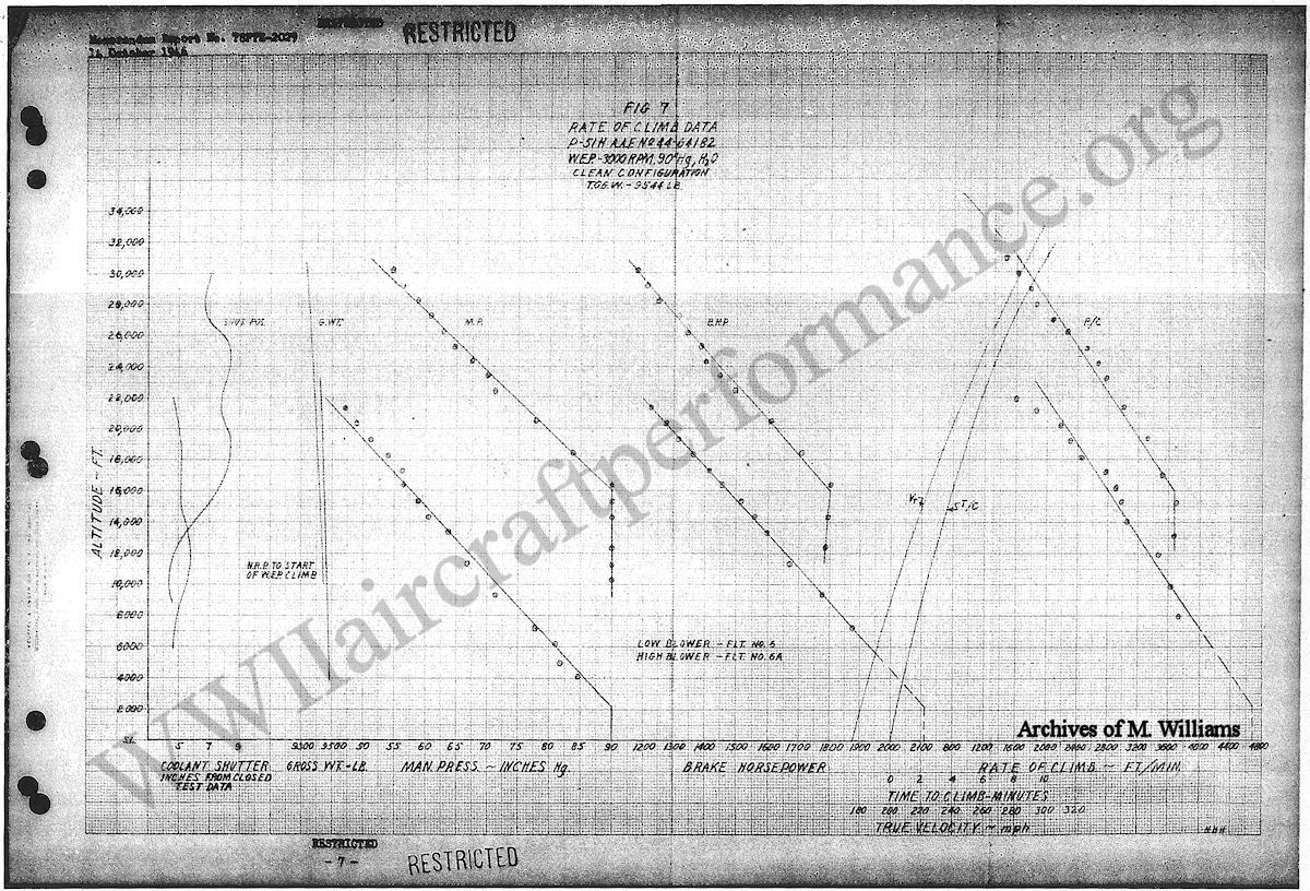
                   The critical altitudes for normal rated power climb (46" Hg., MP and 2700 rpm) are 17,400 ft. for low blower and 30,700 ft. for high blower. The critical altitudes for war emergency power climb (90" Hg., H2O and 3000 rpm) are 16,000 ft. for high blower and by extrapolation, approximately 2200 ft. for low blower.

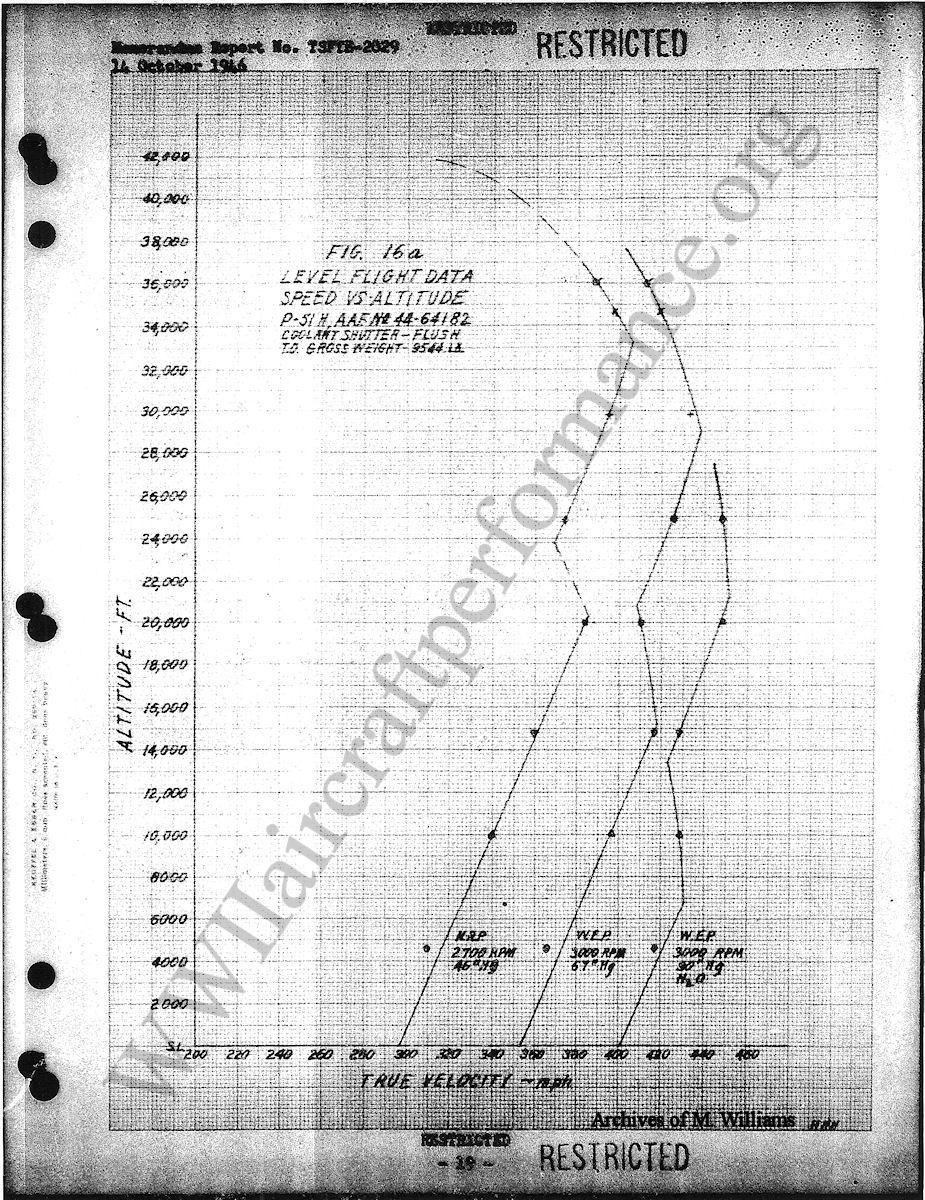
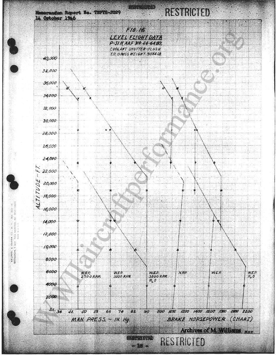
          D.     Maximum Speeds, Coolant Shutters Flush, Wheels and Flaps Up.

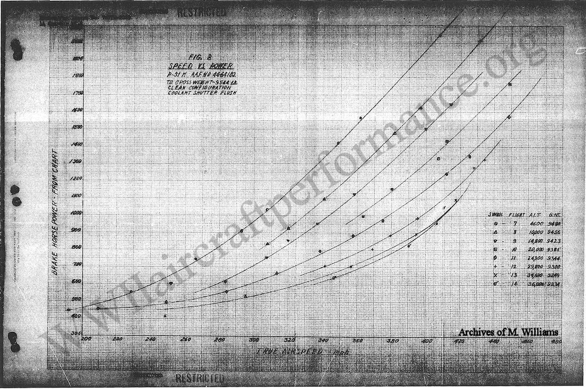
                   1.     Power required curves for the clean configuration at take-off gross weight of 9544 pounds are presented in Figure 8, Appendix I. The maximum speeds under standard conditions are shown graphically in Figure 16a and are tabulated below:

                   2.     Data at war emergency rating with water injection at 3000 rpm.


Altitude Ft.True Air Speed
MPH
MP "Hg.BlowerThrottle
Setting

S.L.40190LowPart   
*680043190LowW. O.
**13400    42390HighPart   
***21200      45190HighW. O.
2500044878HighW. O.

   *Low Blower Critical Altitude for 90" Hg., MP
 **Altitude for Blower Shift.
***High Blower Critical Altitude for 90" Hg., MP.
 
                   3.     Data at military power rating at 3000 rpm, no water injection.
 

Altitude Ft.True Air Speed
MPH
MP "Hg.BlowerThrottle
Setting

S.L.35367LowPart   
1000039667LowPart   
*15200  41867LowW. O.
**20800    40867HighPart   
***29000      43867HighW. O.
3600041347.5HighW. O.

   *Low Blower Critical Altitude for 67" Hg., MP
 **Altitude for Blower Shift.
***High Blower Critical Altitude for 67" Hg., MP.
 
                   4.     Comparative speeds with various airplane configurations at 14,850 ft. at 3000 rpm and 1600 chart brake horsepower.
 

Airplane ConfigurationGross Wt. Lbs.True Speed MPH

Clean9420410
Two 500 Lb. Bombs10410379
Two 110 Gal. Fuel Tanks10900375
Two 1000 Lb. Bombs11410370
Ten Rockets10740367
Six Rockets, Two 550 Lb. Bombs11230361
Six Rockets, Two 110 Gal. Fuel Tanks11724354


          E.     Climb Tests, Coolant Shutters Automatic, Wheels and Flaps Up.

                   1.     Climb data for normal rated rpm (2700) are shown in Figure 6 of Appendix I and are summarized below. It will be noted that the altitude for blower shift as determined from the rate of climb curve is approximately 22,000 ft. whereas from the brake horsepower curve this altitude is indicated as being 23,500 ft. This discrepancy is attributed mainly to the inaccuracies of power charts for the determination of brake horsepower.


Alitude Ft.True
Air
Speed
Rate
of Climb
Min.
Time
of Climb
Min.
MP
"Hg.
BlowerThrottle
Setting

S.L.1641740    .046LowPart   
100001911810  5.446LowPart   
*17400  2151860  9.646LowW. O.
**21700    220141012.346HighPart   
***30700      254138018.646HighW. O.
36000282  72023.239HighW. O.

   *Low Blower Critical Altitude for 46" Hg., MP
 **Altitude for Blower Shift.
***High Blower Critical Altitude for 46" Hg., MP.
 

                   2.     Climb data for war emergency power rating (3000 rpm with water injection) are shown in Figure 7, Appendix I and are summarized in the following table. Separate flights were made to obtain low and high blower rates of climb because of the time limit on engine operation at high powers and the small water supply.


Alitude Ft.True
Air
Speed
Rate
of Climb
Min.
Time
of Climb
Min.
MP
"Hg.
BlowerThrottle
Setting

S.L.1754680   .090LowPart   
  220018146800.590LowW. O.
  960020236602.290HighPart   
1600022436804.090HighW. O.
3000028317209.453.5HighW. O.


          F.     Fuel Consumption. Coolant Shutter Flush, Wheels and Flaps Up.

                   1.     Fuel consumption throughout the operating range of speeds and altitude of the airplane in the clean configuration I shown in Figure 9 and 9a as Fuel flow – Lb/Hr. versus Brake Horsepower. The difference between specific fuel consumption at 14,800 ft. comparing Figures 10 and 14 should be noted and it is recommended that the values of Figure 14 be used since the data is supported by six flights whereas Figure 10 results were obtained from one flight only. Complete information in air miles per gallon versus true airspeed is contained in Figure 11 and the maximum values of miles per gallon obtained during the tests and the corresponding speed are tabulated below.


Altitude Ft.Air Miles per gal.True Speed MPHBlowerGross Wt. Lbs.

  46004.25226Low9485
148005.00267Low9425
249004.80287High9340
298005.22332High9300
346005.10338High9250
360004.97338High9235

 
                   2.     Fuel consumption for the "External Configurations" at 14,850 ft. is shown in terms of Fuel Flow – Lb/Hr. versus Brake Horsepower, Specific Fuel Consumption – Lb/Hp/Hr. versus Brake Horsepower and Air Miles per Gallon versus True Airspeed in Figures 13, 14 and 15 respectively.

          G.     Stalling Speeds.

                   Precision measurements of stalls for the determination of lift coefficients were not obtained. The following approximate stalling speeds were reported for a take-off gross weight of 540 lbs. without any bombs, rockets or external fuel tanks installed.


ConfigurationIndicated
Stalling
Speeds MPH
Approx.
Power
Setting

Cruise1062300 rpm, 36"   
Climb, NRP1002700 rpm, 46"   
Approach for Landing972000 rpm, 23"   
Landing102Power off, Flaps
and Gears Down


          H.     Take-off and Landing Tests.

                   1.     Take-off and landing data was originally obtained on the P-51H, AAF No. 44-64182 airplane but because of difficulty in reading the camera film due to haze in the background and faulty brakes in information was discarded and the tests rerun on P-51H, AAF No. 44-64703. The take-off and landing distances and speeds were measured by the camera method. All distances and speeds are corrected to a gross weight of 9500 lbs. The data is presented in Figure 19 and the principal results are tabulated below.

                   2.     The take-offs were made at 3000 rpm and 61" Hg. MP with the wing flaps neutral. The airplane was not equipped with a sensitive airspeed indicator and, therefore, the reported values of indicated airspeed must be regarded as approximations.


Indicated Airspeed
At Take-off MPH
True Airspeed
At Take-off MPH
Ground Roll
Feet
Total Distance
Over 50' Obst. Feet

12012817302740
  9511514002310


                   3.     Landing tests were made using full flaps. The pilot was unable to obtain indicated airspeeds at contact and the gliding speed at the 50 foot obstacle was recorded instead.


Indicated Airspeed
At 50' Obst. MPH
True Airspeed
At Contact MPH
Ground Roll
Feet
Total Distance
From 50' Obst. Feet

11599.514603390


          I.     Cooling Shutter Tests

                   1.     When in the automatic position the coolant shutter position is regulated by a thermostat which keeps the coolant temperature within the desired range of approximately 100° to 110° C. This position is usually near the flush position and for all level flights the shutter was manually set in the flush position. The maximum coolant temperature of 125° C was not exceeded under standard temperature conditions, when flown with war emergency power. The coolant temperature stayed within the desired range for most power settings, dropping below the desired temperature at very low engine power.

                           Climbs were run in the automatic position. The shutter positions are presented in Figures 6 and 7. The coolant temperatures are presented in the observed data tables of Appendix II.

                   2.     The effect of coolant shutter positions on coolant temperature, airplane speed and rate of climb is shown in Figures 17, 17a and 18.

          J.     Curves

                   All performance curves are included in Appendix I and the results have been reduced to NACA standard atmospheric conditions except where otherwise noted.

          K.     Original Data.

                   The observed test data corrected for instrument error only is contained in the tables and Appendix II.

VII       General Dimensions and Photographs.

                   General Dimensions and photographs are included in Appendix III.


APPENDIX I
 
PERFORMANCE CURVES

Figure 1Airspeed Calibration
Figure 2Free Air Temperature Variation with Vt2
Figure 3Free Air Temperature Calibration
Figure 4Altimeter Calibration
Figure 5Sawtooth Climbs
Figure 6Rate of Climb Data, NRP
Figure 7Rate of Climb Data, W. E. P.
Figure 8Power Required, Clean Configuration
Figure 9Fuel Consumption, Clean Configuration
Figure 9aFuel Consumption, Clean Configuration
Figure 10Specific Fuel Consumption, Clean Configuration
Figure 10aSpecific Fuel Consumption, Clean Configuration
Figure 11Air Miles per Gallon, Clean Configuration
Figure 12Power Required, External Configuration
Figure 13Fuel Consumption, External Configuration
Figure 14Specific Fuel Consumption, External Configuration
Figure 15Air Miles per Gallon, External Configuration
Figure 16Level Flight Data
Figure 16aLevel Flight Data
Figure 17Coolant Shutter Calibrations (Speed vs Shutter Position)
Figure 17aCoolant Shutter Calibrations (Speed vs Shutter Position)
Figure 18Coolant Shutter Calibration (R/C vs Shutter Position)
Figure 19Take-Off and Landing Data
 

WWII Aircraft Performance   Mustang Performance Trials